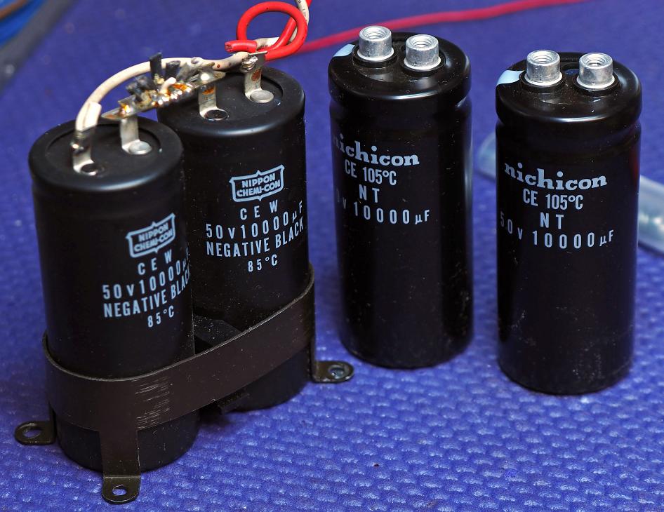
These are brand new supply capacitors. A perfect drop-in fit. I
prefer the screw terminal because they don't require creating
large solder joints, and all the mess that goes with it... flux,
flux clean-up, and lots of heat.
prefer the screw terminal because they don't require creating
large solder joints, and all the mess that goes with it... flux,
flux clean-up, and lots of heat.
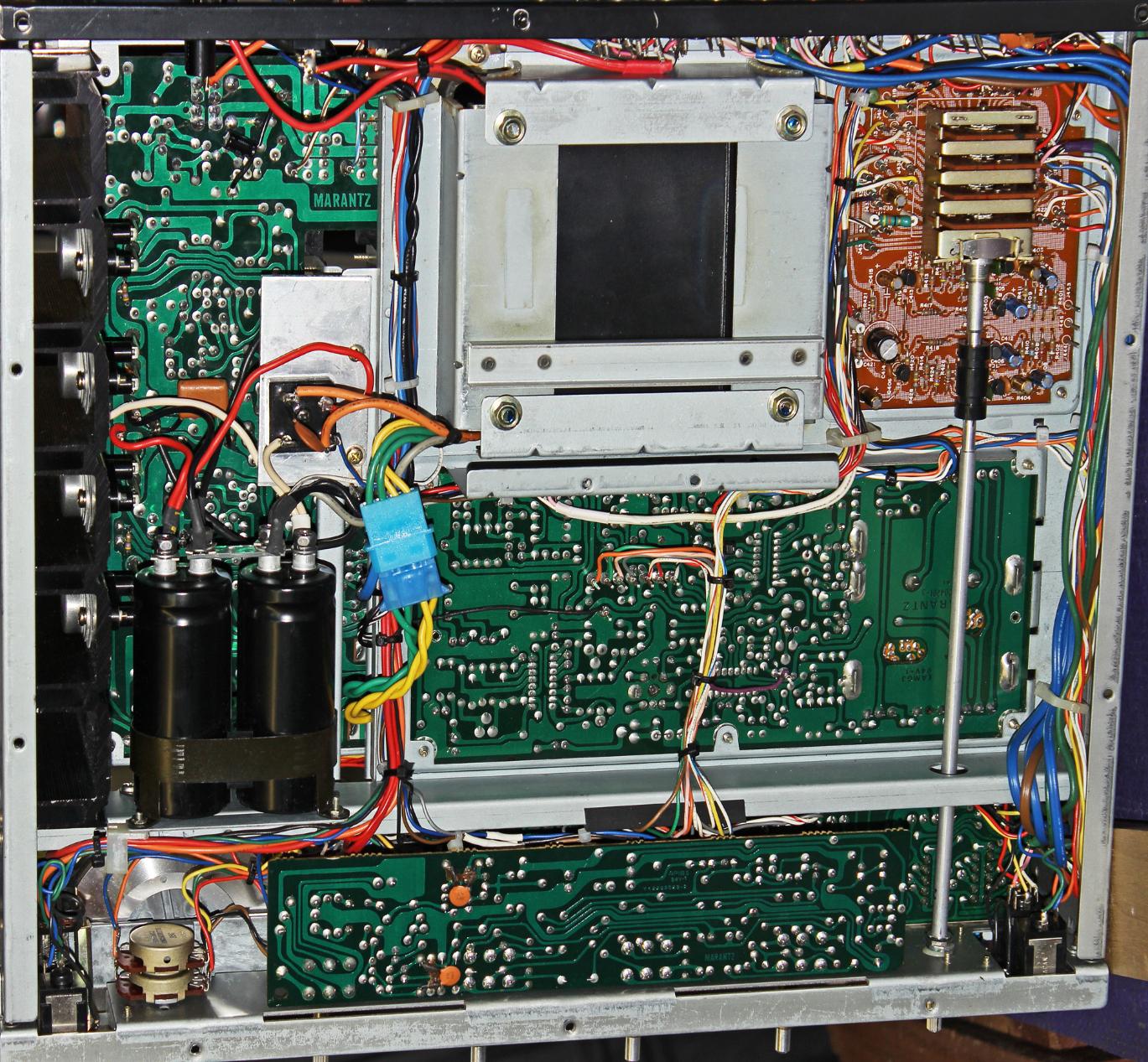
Here is a bottom view of the completed unit. Notice the quick disconnect on the power supply wires. This makes removing the transformer much easier. All boards are cleaned to
remove dust, grime and flux and they are now shiny bright.
The selector switch (right) is a four stack switch, hence, my concern with a robust fix to this board. Luckily, the board was not severely compromised. It affected the traces only near
the front wafer. The integrity of the board was still intact. The compromised traces were reinforced with 26ga wire. This was probably over-kill, but I stand behind my work so I never
want this to be a source of issues... that's just the way I roll.
The wires are all routed in the frame channels or bundled into a nice harness. Nearly every wither that was laid across the top side of the receiver was re-routed and/or replaced to
allow the wires to be harnessed in the frame. This is the way the unit should have been... and would have been assembled in an earlier generation. Each wire-wrap post had to be
de-soldered, pushed through to the bottom side of the board and re-soldered. If the wire was too short it was replaced (same color) to allow it to be routed through the harness on the
bottom. It is much cleaner, allowing for better access to the boards, and as you will see on the following page, looks much... much better.