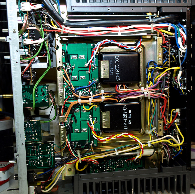
Here you can see where I am removing the main supply caps. The sequence of the pictures are a bit out of order here as I
removed these prior to doing any work on the outputs, but I wanted to show the state of the rectifier boards here, which is
what I am going to work on next. Understand that all the wiring and work on this uint was completed prior to installing the
supply caps back into the unit. Installing the supply caps was the very last task (more on that later). Notice I have clipped the
leads to the output sections. This is to protect them while I desoldered the cap joints.
There are several caps on one board (one bi-polar). These can be replaced without removing the board form the unit. This
saves us from having to remove all the wires that are anchored to it. It is tight work, but can be done, working through the
capacitor hole (from the top side) and from the sides. Capacitor orientation must be checked and rechecked!!!
After the caps are replaced, you can clean the boards. As a last step, inspect all the components and wires. Make sure they
are aligned, connected and in proper position. A lot can happen when working in tight places.


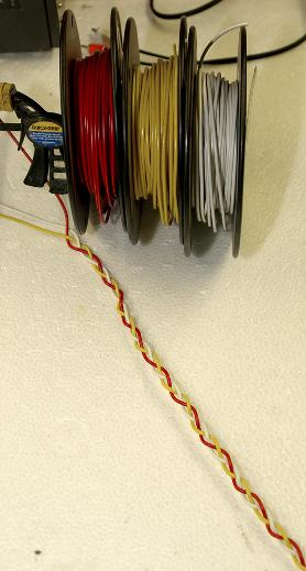
Here are some shots of the bottom side of the unit after it was all complete (new supply caps installed... more on that later).
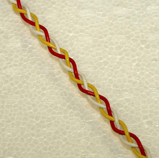
Wiring has been bundled and routed. Notice the new leads to the output sections. This had twisted leads originally (see top
photo). I created braided leads using 20ga wire to minimize induction.
Wiring has been bundled and routed. Notice the new leads to the output sections. This had twisted leads originally (see top
photo). I created braided leads using 20ga wire to minimize induction.