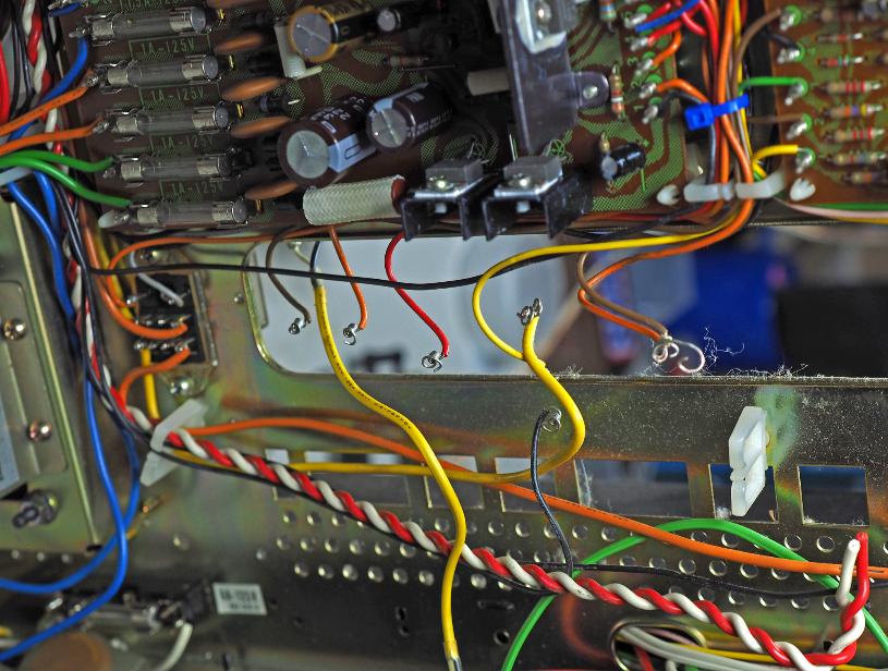
Pulling the output section requires disconnecting wires. Use a wire
un-wrap tool for this.
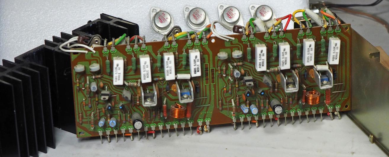
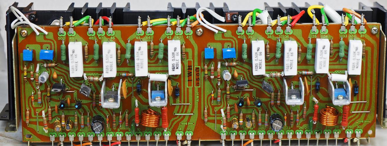
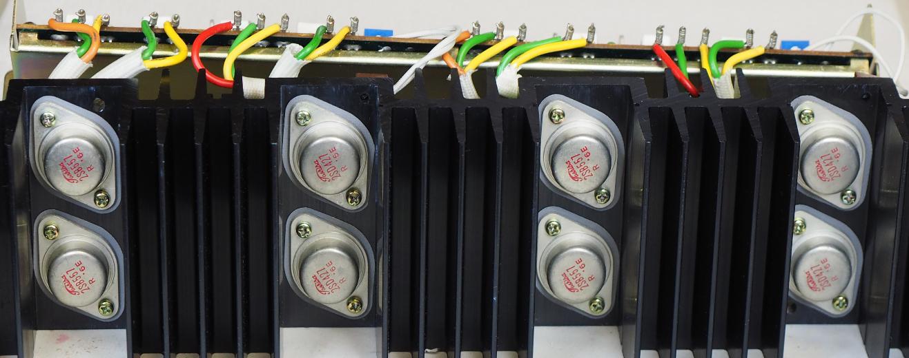
Below, the section is disassembled, cleaned and re-assembled.
Remember, be careful not to move the STV-4H diodes around too
much (the little horseshoe shaped components at the top of the
board that attach to the heat sync). The leads can break off at the
diode with too much flexing. These have been out of production
for a long time and little can be done if they get broke. I loosen the
screws and separate them from the heat sync by moving the wire
nearest the board instead of flexing the component itself. Once
disassembled, I handle the board in such a way as to minimize
movement to these components.
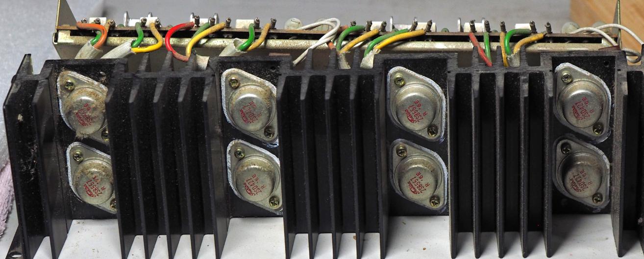
The same can be said for the TO-3 transistor sockets wired to the
top of the board. This is heavy 20ga wire and will take a lot more
abuse but I have still seen these wires break off at the wrap posts
(it does not take too much flexing to get a wire to break). The good
news here is that if one does break, it can be repaired with a little
time and effort. But the proper fix requires the correct color coded
wire in 20ga, and un-wrap/wrapping tools.
So just handle the board carefully and save yourself a lot of
frustration.
New trimmers, new audio caps, new sil-pads for output transistors
and new heat compound for the on-board transistor syncs.
un-wrap tool for this.
Below, the section is disassembled, cleaned and re-assembled.
Remember, be careful not to move the STV-4H diodes around too
much (the little horseshoe shaped components at the top of the
board that attach to the heat sync). The leads can break off at the
diode with too much flexing. These have been out of production
for a long time and little can be done if they get broke. I loosen the
screws and separate them from the heat sync by moving the wire
nearest the board instead of flexing the component itself. Once
disassembled, I handle the board in such a way as to minimize
movement to these components.
The same can be said for the TO-3 transistor sockets wired to the
top of the board. This is heavy 20ga wire and will take a lot more
abuse but I have still seen these wires break off at the wrap posts
(it does not take too much flexing to get a wire to break). The good
news here is that if one does break, it can be repaired with a little
time and effort. But the proper fix requires the correct color coded
wire in 20ga, and un-wrap/wrapping tools.
So just handle the board carefully and save yourself a lot of
frustration.
New trimmers, new audio caps, new sil-pads for output transistors
and new heat compound for the on-board transistor syncs.