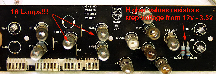
I replaced all 16 bulbs in the light board. After assembly I was disappointed in the lack-luster appearance of
the display. The yellow cast of the incandescent lamps left a lot to be desired. So I converted the whole
setup to color coded LED
the display. The yellow cast of the incandescent lamps left a lot to be desired. So I converted the whole
setup to color coded LED
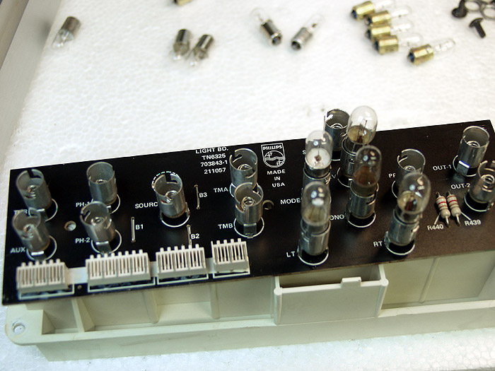
The Lighting Project
I started by pulling all the bulbs and sockets. The output 1 and 2 lamps on the right are driven by 12VDC,
through the 120 ohm resistors on the board. The power supply already has a 12v DC output for this.
Converting this was a simple task of upping the resistor values to cut the voltage to 3.5v. The rest of the
lamps took a little more effort. Below I have started the upgrades to the board.
through the 120 ohm resistors on the board. The power supply already has a 12v DC output for this.
Converting this was a simple task of upping the resistor values to cut the voltage to 3.5v. The rest of the
lamps took a little more effort. Below I have started the upgrades to the board.
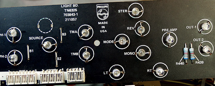
Completed board below, looks much cleaner without all that hardware...
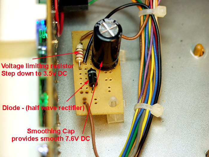
My miniature power supply....
The bulbs are 6v AC. The power supply supplies an 8VAC feed to these lights (which compensates for the
resistance voltage drop across the lamps). I built a small half-wave rectified power supply and mounted it just
behind the light board. It is spliced into the 8VAC feed (brown wire) with a ground (black) for the smoothing
capacitor. It produces a smooth 3.5VDC output. I then added a couple of jumpers on the light board so the
current flow was not series across a along string of LEDs. Works very well, and dresses up the display to look
waaaaayyy cool...
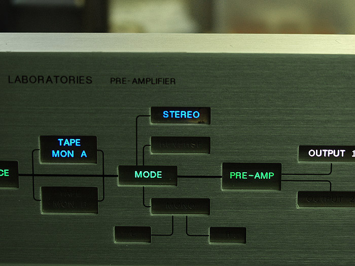
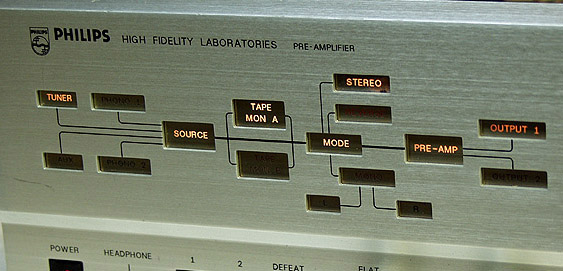
Cool green, blue, and white for the output indicators...
Green (tuner, Aux, Phone 1 & 2, Source, Mode, Pre-Amp), Blue (Tape
Mon A & B, Stereo, Mono, Reverse, R & L), White (Output 1& 2)
Green (tuner, Aux, Phone 1 & 2, Source, Mode, Pre-Amp), Blue (Tape
Mon A & B, Stereo, Mono, Reverse, R & L), White (Output 1& 2)