Adjustments

This oscilloscope setup is used to measure amplifier gain and adjust the output balance. This amplifier has a
pot mounted on the board for each channel that allows you to balance the output gain on the two pre-drive
transistors. This ensures the audio signal has equal amplitude on both sides (+/-) of the oscillating frequency.
pot mounted on the board for each channel that allows you to balance the output gain on the two pre-drive
transistors. This ensures the audio signal has equal amplitude on both sides (+/-) of the oscillating frequency.
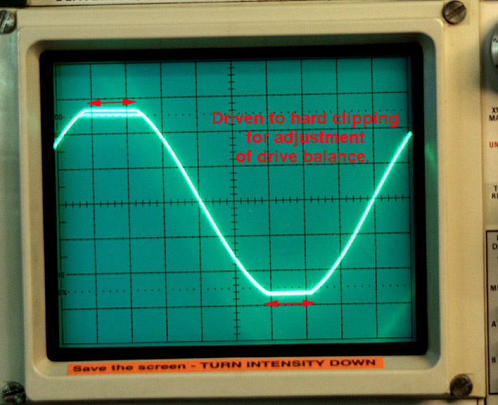
Here, the amp is driven to clipping. The adjustment is made so that clipping occurs equally on both +/- sides
of the wave form. The camera picked up a bit of scope flicker at the top of one wave form, but you can see
that both positive and negative sides peak at 26v, and show two vertical subdivisions (dots) on each side of
the peak.
of the wave form. The camera picked up a bit of scope flicker at the top of one wave form, but you can see
that both positive and negative sides peak at 26v, and show two vertical subdivisions (dots) on each side of
the peak.

Clean sinoidal wave to 25v peak (this is 39 wpc RMS). Clipping starts uniformly on both +/- sides.
This is good!!!
This is good!!!
Bias is set to 7mv...
Cold, the bias runs about 5mv and rises to 7mv as it reaches a stable operating temperature.
Cold, the bias runs about 5mv and rises to 7mv as it reaches a stable operating temperature.